
 E-mail :
 Call Us :
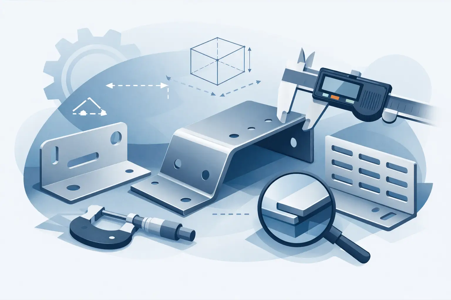
A drawing can call for a bracket that is 12.00 inches long, with two mounting holes positioned within ±0.005 inch. But if that bracket is cut, formed, welded, powder coated, and measured without a clear inspection plan, the stated dimensions alone do not guarantee fit or function. This sheet metal tolerancing guide explains how engineers and procurement teams can set practical requirements that protect assembly performance without creating avoidable production cost or lead-time risk.
For OEM components, construction hardware, support systems, and custom fabrications, tolerancing is not simply a drawing exercise. It determines process selection, tooling strategy, inspection methods, material yield, and the likelihood that parts from different production lots will assemble correctly. The best tolerance is not the tightest value. It is the value that controls the feature that matters.
Why Sheet Metal Tolerances Need Process Context
Sheet metal is not machined billet material. It moves during cutting, bending, welding, forming, and finishing. Material thickness can vary within the mill specification, bends can introduce springback, and heat from welding can pull a fabricated assembly out of position. A tolerance that is reasonable for one process may be impractical or unnecessarily expensive for another.
For example, a laser-cut hole pattern can be held more closely than the overall dimensions of a large welded frame. Likewise, a formed flange angle depends on material grade, thickness, bend radius, grain direction, and bend length. Asking for identical tolerances across every feature can force secondary operations where they provide no functional benefit.
A production-ready drawing separates critical interfaces from general geometry. Hole centers that locate an electrical enclosure, a slotted connection in a strut-compatible system, or a post base mounting pattern may require close control. The outside edge of a non-mating cover panel may not. This distinction allows the manufacturer to focus inspection and process control where the application needs it most.
Sheet Metal Tolerancing Guide: Start With Function
Before assigning numerical limits, identify how the part works in the finished assembly. Ask whether a feature locates another component, provides clearance, carries load, seals against weather, accepts a fastener, or serves only an appearance requirement. Each answer points to a different tolerancing approach.
A mounting hole should be specified from the datums that represent the actual installation condition. If a bracket mounts against a vertical face and is located by two fasteners, the mounting face and primary locating hole pattern are generally more meaningful references than an arbitrary outside corner. Datum selection should reflect how the component is fixtured, assembled, and inspected.
When fit is driven by clearance, consider the full stack-up rather than the part in isolation. A bolt must pass through the combined variation of the hole diameter, hole position, mating-hole position, fastener size, and any coating buildup. A tolerance that appears adequate on one drawing can fail once all related component variation is considered.
Where a feature is not functionally critical, use a general tolerance note instead of individually tolerancing every dimension. This makes drawings easier to read, supports efficient manufacturing, and reduces the chance of conflicting requirements. General tolerances should still be appropriate to the material, part size, and fabrication route.
Match Tolerances to the Manufacturing Process
Cutting and hole-making
Laser cutting, punching, and CNC cutting can produce accurate profiles and repeatable hole locations when material is properly supported and programmed. The achievable result depends on sheet thickness, material type, part size, machine condition, nesting, and feature geometry.
Small holes, narrow slots, and closely spaced features require particular attention. A practical rule is to avoid holes that are too small relative to material thickness, especially when punching. Very narrow webs between holes or between a hole and a formed edge can distort during fabrication. If the application requires an unusually small or precise feature, reaming, machining, or a dedicated secondary operation may be the better choice.
Hole position often matters more than hole size. For a four-hole mounting pattern, specifying each hole from a common datum scheme is more effective than controlling only the spacing between neighboring holes. It prevents the pattern from shifting as a group while still meeting local dimensions.
Bending and forming
Bending introduces variables that a flat pattern cannot fully eliminate. Springback varies by material and temper. Thicker material and larger bend radii typically increase the range of possible results, while long bends can show more variation from one end to the other.
Tolerances for formed parts should account for both the bend angle and the flange dimensions. If a flange must seat against another component, the angle may be functionally critical. If the flange simply adds stiffness, a broader angle range may be acceptable. When a bend-to-hole location is essential, dimension it from the formed datum or clearly state the inspection condition. A hole located close to a bend can shift as the material forms.
Bend radius should also be specified deliberately when it affects strength, appearance, fit, or a mating component. Otherwise, allowing a manufacturer-standard inside radius that suits the material and tooling can improve consistency and cost control.
Welding and fabricated assemblies
Welded assemblies need tolerance planning that recognizes heat distortion. Even with controlled fixtures and qualified welding practices, a large frame, base, channel assembly, or structural bracket can move as welds cool. The more weld metal applied, the greater the potential effect.
Specify the critical mounting faces, hole patterns, and overall alignment requirements, then allow reasonable variation on noncritical edges. For precision interfaces, manufacturers may use weld fixtures, controlled weld sequences, post-weld straightening, or machining. These methods can deliver close results, but they add time and cost. They should be reserved for requirements that genuinely affect installation or performance.
Flatness, straightness, perpendicularity, and parallelism are especially useful for welded parts when they are tied to a real functional need. A post base that must sit flat on concrete may need a defined base-plane flatness requirement. A cosmetic weldment with no sealing or alignment function may not.
Surface finishing and coatings
Finishing is part of the dimensional condition of the finished component. Galvanizing, powder coating, plating, and painted finishes add thickness that can affect threads, slots, close-fitting holes, and mating surfaces. Coating buildup is often uneven around sharp corners, internal profiles, and threaded areas.
If a part must assemble after finishing, state whether dimensions apply before or after coating. Masking, oversized holes, tapped-after-coating features, or compatible fastener selection may be necessary. For corrosion-resistant outdoor hardware, the correct approach is usually to design the clearance into the component rather than treating coating thickness as an afterthought.
Use GD&T Where It Clarifies the Requirement
Geometric dimensioning and tolerancing can be valuable for parts with critical interfaces, repeated assemblies, and complex position requirements. It is not necessary to apply GD&T to every fabricated part, but it can reduce ambiguity when conventional plus-or-minus dimensions become difficult to interpret.
Position tolerance is particularly useful for mounting patterns because it controls the location of a feature relative to defined datums. Profile tolerance can control a laser-cut contour or formed shape. Flatness controls a surface without requiring a datum, while perpendicularity and parallelism relate one feature to another.
The value of GD&T depends on clear datum selection and practical inspection. A callout that cannot be measured consistently at the supplier or receiving facility creates disputes instead of control. For high-volume or safety-critical components, the inspection approach should be agreed upon during design review, not after the first lot is delivered.
Avoid Tolerance Problems Before Production
Many tolerance issues originate when the RFQ package lacks the information needed to understand the part's intended use. A reliable package includes the drawing revision, material grade and thickness, finish requirements, critical dimensions, and any mating-part information that affects fit.
For new components, a first article inspection is an effective way to verify dimensions, bend conditions, weld geometry, finish coverage, and assembly fit before full production. For repeat programs, documented inspection points and approved samples help maintain consistency across lots.
Communication matters when an engineering change affects a critical feature. Moving a hole by a small amount, changing material from mild steel to stainless steel, or adding a coating can alter forming behavior and fit. A capable manufacturing partner reviews these changes in relation to the complete fabrication sequence, not as isolated drawing edits.
Balance Precision, Cost, and Lead Time
Tighter tolerances can require slower cutting parameters, more frequent inspection, dedicated tooling, precision fixtures, secondary machining, or additional handling. These controls are justified for a locating surface, a safety-critical connection, or a component that must interchange across an OEM product line. They are less justified for dimensions that do not affect fit, strength, or appearance.
The objective is repeatable production at the tolerance the application requires. Procurement teams benefit when drawings clearly distinguish critical-to-function features from general features, because quotes become more comparable and suppliers can select the right production method from the start.
Metallix Exports supports this approach through precision cutting, punching, bending, welding, forming, assembly, and finishing capabilities for standard hardware and custom fabricated components. Early manufacturability review can identify where a tolerance needs tighter control, where a design can be simplified, and where inspection should be concentrated to support dependable production and on-time delivery.
A well-toleranced sheet metal part gives the production team a clear target without asking the process to do what the application does not require. When functional datums, realistic process limits, and finished-condition requirements are aligned, buyers gain parts that fit reliably, programs that move faster, and quality that holds from the first shipment through repeat production.