 E-mail :
 Call Us :
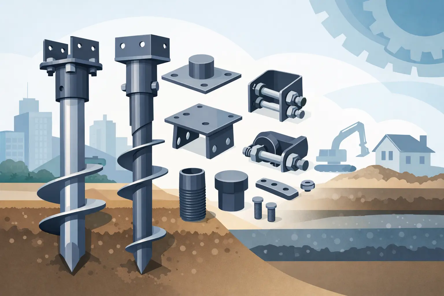
A helical pier assembly can look straightforward on a procurement sheet: a lead section, extensions, couplers, helices, and a termination bracket. Yet the consequences of specifying the wrong combination are significant. Knowing how to choose helical pier hardware means aligning every component with the project’s soil profile, required capacity, structural connection, corrosion exposure, and installation method - not simply selecting the largest shaft or lowest unit price.
For contractors, OEM buyers, engineers, and procurement teams, the goal is hardware that installs predictably, transfers load as designed, and remains durable throughout its intended service life. The right specification also reduces field changes, split shipments, and delays caused by mismatched components.
Start With the Foundation Design Criteria
Helical pier hardware should be selected from verified project requirements, beginning with the factored or allowable compression and tension loads the foundation must support. A pier designed only for compression may require a different shaft configuration, helix arrangement, and bracket connection than one resisting uplift, overturning, or cyclic loading.
The loading condition is only one part of the design basis. Engineers should define the required installation depth, expected torque range, lateral demand, settlement limits, and the type of supported structure. A light equipment pad, solar support, modular building, retaining application, or elevated deck may each require a different pier configuration even where the nominal vertical load appears similar.
Do not treat installation torque as a standalone capacity value. Torque can be a valuable field indicator when it is correlated to the selected pier system and site conditions, but soil variability, equipment calibration, and installation practices affect the result. Capacity verification should follow the project engineer’s criteria and applicable testing or acceptance requirements.
Compression, tension, and lateral loading
Compression capacity is commonly associated with the bearing resistance developed by the helix plates in suitable bearing strata. Tension capacity depends on soil resistance above the helices and on the tensile strength of the complete load path, including couplers and brackets. Lateral load often requires additional consideration because a slender shaft may perform differently under side load than under purely vertical loading.
Where lateral movement or moment is meaningful, the solution may involve a larger shaft, a stiffer connection detail, bracing, multiple piers, or another engineered foundation arrangement. Hardware selection should support the complete structural design rather than isolate one catalog rating.
Review Soil Data Before Selecting Helices
Soil conditions determine whether a helical pier can be installed efficiently and where the helices should terminate. Bore logs, geotechnical reports, test data, and local installation experience should be reviewed before finalizing lead section geometry.
Helix diameter and the number of helixes influence bearing area, installation resistance, and the ability to reach the target stratum. Larger helixes are not automatically better. They may create excessive torque demand in dense soils, encounter obstructions, or be unsuitable for the available drive equipment. In soft or loose soils, a larger projected area or multiple helixes may be needed to achieve the required capacity at a practical depth.
Helix spacing also matters. Spacing must allow each helix to develop its intended resistance without excessive interaction with adjacent helixes. The selected configuration should reflect the site’s soil layers rather than relying on a standard arrangement used on an unrelated project.
Groundwater, fill material, cobbles, buried debris, frost depth, and expansive soil behavior can change the selection decision. If the information is limited, the procurement team should not compensate by making assumptions about pier size. Early coordination with the engineer and hardware manufacturer is more reliable than correcting a failed installation plan after equipment reaches the site.
Select the Shaft and Couplers as a Load Path
The central shaft carries installation torque and transfers structural loads from the bracket to the helical lead section. Its shape, wall thickness, steel grade, and connection style must be appropriate for both the installation demand and the completed foundation load.
Round shaft and square shaft systems are selected for different applications and manufacturer designs. The proper choice depends on required torque, compression and tension capacity, connection details, and available installation tooling. A shaft that is adequate for final service load may still be unsuitable if it cannot safely transmit the torque needed to reach competent bearing soil.
Extensions should match the lead section system exactly. Mixing shafts, couplers, bolts, or hardware from incompatible product families can introduce fit-up problems and unverified capacities. This risk is especially relevant for buyers sourcing hardware from multiple vendors or replacing only part of an existing system.
Pay close attention to connection hardware
Couplers, splice bolts, nuts, and welded connection details deserve the same scrutiny as the shaft itself. These components experience significant force during installation and service. Specify compatible fastener grades, hole patterns, bolt diameters, torque requirements, and inspection expectations.
A reliable supplier should provide dimensional consistency across lead sections, extensions, and termination components. Tight tolerances help installers assemble sections efficiently in the field and help purchasing teams avoid costly nonconforming inventory. For custom projects, connection details should be reviewed against approved drawings before production begins.
Match the Top Bracket to the Supported Structure
The top connection is where the pier becomes part of the structure. A generic bracket may not suit a column base, grade beam, timber post, steel frame, precast member, or retrofit underpinning application. The bracket must transfer the intended compression, tension, shear, and, where applicable, moment without creating eccentric loading that the design did not consider.
Confirm the supported member dimensions, anchor hole layout, weld requirements, adjustment range, and installation access. Adjustable brackets can be useful where final elevation must be fine-tuned, but they should be selected based on approved load ratings and not simply for convenience. Fixed brackets may offer a more direct and rigid connection when elevations and geometry are well controlled.
For fabricated steel structures, custom helical pier brackets can simplify site assembly by matching the actual column or frame interface. Metallix Exports can manufacture structural hardware to project drawings, supporting buyers who need standardized quality alongside application-specific fabrication.
Specify Corrosion Protection for the Actual Exposure
Corrosion protection is a design decision, not a finishing preference. Soil chemistry, moisture, salinity, industrial contamination, coastal exposure, and the intended design life all affect the required protection level.
Hot-dip galvanizing is widely used for helical pier hardware because it provides a durable protective coating for many ground-contact applications. However, galvanized hardware is not a universal answer. Highly corrosive soils, marine environments, and long-life infrastructure work may require increased steel thickness, specialized coatings, corrosion allowances, cathodic protection, or a different material strategy.
Ask for clear documentation of coating requirements, coating thickness targets where applicable, and treatment of field-welded or damaged areas. Also consider the entire assembly. A well-coated lead section does not solve a durability issue if bolts, brackets, or extensions have lower corrosion resistance.
Confirm Installation Equipment and Field Practicality
The best hardware specification still needs to work with the contractor’s installation equipment. Confirm drive head compatibility, torque capacity, adapters, access limitations, and the expected range of extension lengths. Restricted headroom, tight property lines, sloped terrain, or work near existing structures can affect both hardware selection and installation sequencing.
The project should also define how installers will monitor depth, inclination, torque, and final elevation. Poor alignment can reduce the effectiveness of the connection and complicate bracket installation. Establishing acceptance criteria before work begins gives the contractor, engineer, and owner a common basis for evaluating each installed pier.
Field conditions can require adjustments, but substitutions should be controlled. Changing helix diameter, shaft size, extension type, or bracket configuration without engineering review can alter the load path and invalidate assumptions behind the original design.
Buy as a System, Not as Separate Parts
For B2B procurement, helical pier hardware is more reliable when sourced as a coordinated system. Lead sections, extensions, couplers, fasteners, brackets, and protective finishes should be specified together, with part numbers, drawings, material requirements, and inspection criteria clearly defined.
A complete purchasing package typically identifies required quantities by pier configuration, manufacturing tolerances, steel grades, surface finish, packaging method, marking requirements, and shipment schedule. For export projects, packaging and documentation matter as much as production quality. Hardware should arrive organized for identification, handling, and staged installation rather than as mixed components that create site delays.
Price comparisons should account for more than the piece cost. Inconsistent dimensions, missing connection hardware, unclear coating requirements, and late deliveries can quickly outweigh a lower initial quote. A capable manufacturing partner supports repeatable production, quality checks, and practical communication when project requirements change.
Make the Final Selection With Verified Information
The most effective helical pier specification is built from soil data, structural loads, corrosion conditions, installation constraints, and a complete connection design. It should state what the hardware must achieve, not merely describe what it looks like.
When those requirements are documented early, buyers can source with confidence, installers can work with fewer interruptions, and project teams can protect both schedule and foundation performance. The right hardware is the hardware that fits the engineered system, the field conditions, and the long-term demands of the structure.