
 E-mail :
 Call Us :
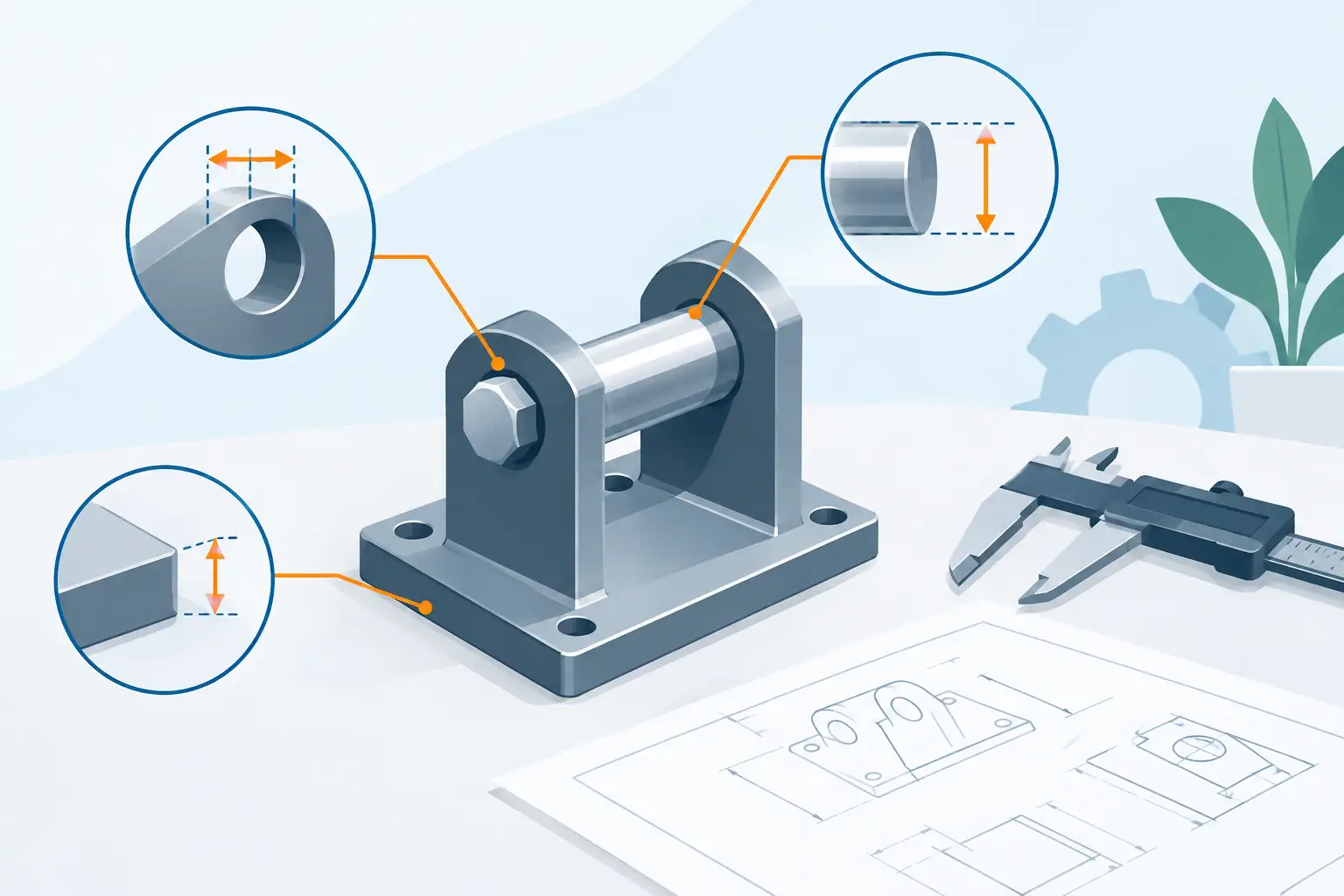
A bracket can meet every individual part dimension on its drawing and still fail at installation. Holes may not align with a mating frame, a welded assembly may sit out of square, or a finished part may bind after coating. This guide to fabricated assembly tolerances explains how to control those outcomes before they become costly fit-up issues, field rework, rejected shipments, or production delays.
For OEMs, contractors, and procurement teams, tolerance planning is not only an engineering exercise. It determines whether components assemble consistently across production lots, whether replacement parts remain interchangeable, and whether a project can move from receiving to installation without unnecessary adjustments.
What Fabricated Assembly Tolerances Control
A tolerance is the permitted variation from a nominal dimension. In fabricated assemblies, however, the requirement is larger than any one dimension. The assembly must achieve its intended fit, alignment, function, and appearance after cutting, punching, bending, welding, hardware insertion, surface finishing, and final handling.
A fabricated channel, for example, may require a controlled flange width so it accepts compatible fittings. A post base may need accurate anchor-hole locations so it installs over a concrete layout. A marine hardware assembly may need parallel faces and consistent clearances to carry load without premature wear. Each application calls for a tolerance strategy tied to functional interfaces rather than a blanket demand for the tightest possible numbers.
The central question is straightforward: which dimensions affect assembly, safety, load transfer, adjustment, or customer-facing appearance? Those dimensions deserve deliberate control. Other dimensions may allow more variation without compromising the product.
Why Individual Part Tolerances Are Not Enough
Fabricated assemblies accumulate variation. A laser-cut blank has cutting variation. Press brake forming adds bend-angle, flange-length, and springback variation. Welding introduces heat distortion, shrinkage, and positional movement. Coating can alter hole size, thread engagement, and mating clearances.
When each feature is specified independently, the combined variation can be greater than the assembly can accept. This is tolerance stack-up. It is especially relevant in multi-part weldments, adjustable framing hardware, repeated hole patterns, assemblies with purchased fasteners, and products that connect to customer-supplied components.
Consider two formed brackets that mount to opposite sides of a support. If each bend, hole location, and material thickness is allowed to vary in the same unfavorable direction, the installed gap can fall outside the intended range even though both brackets pass separate inspection. Functional dimensions should therefore be evaluated from the assembly datum scheme, not only from the part edge used during fabrication.
Build Tolerances Around Functional Datums
A datum is the reference from which critical features are located and inspected. Well-chosen datums make manufacturing and quality verification more repeatable because they reflect how the part actually locates in service.
For a mounting plate, the primary datum may be its flat bearing surface. A secondary datum may be one edge or a pilot hole that establishes horizontal position. Hole patterns, slots, tabs, and formed features can then be located from those references. For a welded frame, primary datums may be the mounting faces and the interface plane that connects to a larger system.
Avoid locating critical features from a chain of nonfunctional dimensions when a common datum is available. Dimension chains create unnecessary stack-up and make inspection harder to interpret. Baseline dimensions from a common functional reference are usually clearer for both the fabrication team and the customer’s installation team.
Match the Datum to How the Product Is Used
The correct datum depends on the application. A decorative enclosure may reference visible exterior edges. A machinery guard may reference mounting holes and hinge surfaces. A structural connection may reference bearing faces, bolt-hole geometry, and load-path alignment.
This distinction matters when a fabricated part has cosmetic and functional requirements that compete. A visible edge may need a controlled appearance, but it should not become the inspection reference for a hole pattern if the holes are what establish the final installation position.
Set Tolerances That the Process Can Hold
Every process has practical capability limits, and those limits change with material, thickness, part size, geometry, tooling, and production volume. A tolerance suitable for a short, laser-cut stainless steel plate may not be realistic for a long galvanized channel that is formed and welded.
Material behavior is a major factor. Mild steel, stainless steel, aluminum, copper, and galvanized sheet respond differently to forming force, heat input, and springback. Longer bends and narrow flanges generally carry more variation than short, well-supported forms. Thin sheet can distort during welding, while heavy sections may require more heat and create greater localized movement.
Tighter tolerances also increase cost. They can require specialized fixturing, slower setups, additional machining, more frequent inspection, and higher rejection risk. That investment is justified where function demands it, such as precision interfaces, hardware locations, bearing surfaces, or controlled mating assemblies. It is rarely justified on every noncritical edge.
A productive drawing distinguishes between general tolerances and critical features. General tolerances provide reasonable control for ordinary dimensions. Critical dimensions receive explicit limits based on fit and function. This approach protects performance while allowing efficient production.
Account for Bending, Welding, and Finish Early
The most common assembly tolerance problems arise when downstream operations are treated as afterthoughts. A flat pattern may look correct before bending but form into a geometry that requires bend allowances and reliefs. A welded structure may be accurate in its fixture but move after unclamping as residual stresses relax.
Bend radius, material grain direction, inside versus outside dimensions, and flange measurement points should be clear on the drawing. If two bends create a controlled internal opening, define the opening directly rather than expecting it to result from separate flange dimensions.
For welded fabrications, identify which faces, hole patterns, and centerlines must remain controlled after welding. Welding sequence, fixture design, tack locations, heat input, and straightening methods can then be planned around those requirements. Where practical, machining or drilling final critical interfaces after welding may provide better positional control than attempting to preserve every feature through thermal distortion.
Surface finish deserves the same attention. Powder coating, galvanizing, plating, and paint add thickness that can affect close-fit tabs, slots, threaded holes, hinge clearances, and fastener engagement. Masking, post-finish tapping, oversized holes, or defined clearance allowances may be appropriate, depending on the assembly.
Specify Inspection Methods With the Requirement
A tolerance has limited value if it cannot be measured consistently. The drawing or quality plan should state the inspection approach for features where measurement method changes the result. Examples include flatness, perpendicularity, hole position, diagonal squareness, weld distortion, and assembly gap.
A hole center measured from a burr side may not match the same measurement taken after deburring. A long formed part measured on an unsupported table may appear less straight than it does when installed. A weldment checked before it cools can produce a different result than one inspected after stabilization.
For critical assemblies, practical inspection may include go/no-go gauges, fixture checks, coordinate measurement, calibrated height gauges, pin gauges, or a mating component test. A functional gauge is often especially valuable for repeat production because it verifies the condition the customer actually needs: the assembly fits.
Inspection records should focus on the characteristics that matter most. Measuring every possible dimension does not necessarily improve quality. Verifying controlled datums, critical interfaces, and process-sensitive features provides more useful assurance.
Questions to Resolve Before Production
Before releasing a fabricated assembly for production, engineering and sourcing teams should confirm several points: the mating parts and their allowable variation, the primary installation references, the dimensions that affect load or motion, the surface finish and coating allowances, and the inspection method for critical features.
They should also clarify whether the requirement applies to a free-state part or an installed assembly. Some sheet metal parts are designed to flex into position during installation. Others must remain stable without force. Treating those conditions as equivalent can lead to unnecessary disputes during inspection.
For repeat programs, an approved first article or sample assembly is valuable. It confirms that drawings, fixtures, gauges, packaging, and mating components work together before volume production begins. If a design change affects bend geometry, welding sequence, coating, or hardware, the tolerance review should be reopened rather than assumed unchanged.
A Manufacturing Partner’s Role in Tolerance Control
A capable fabrication partner does more than produce to a print. The partner reviews part geometry, identifies stack-up risks, selects process-appropriate controls, and communicates where a requirement may add cost without adding function. This is particularly valuable for customers sourcing custom brackets, structural hardware, channels, weldments, framing systems, and export-ready assemblies from a single supplier.
At Metallix Exports, tolerance control is considered across cutting, forming, welding, assembly, and finishing so that critical interfaces are protected throughout the production route. The objective is quality you can rely on at receiving, on the production line, and at the jobsite.
The best tolerance is not the smallest number on a drawing. It is the controlled range that delivers repeatable fit, dependable function, and efficient manufacturing - every time the assembly is built.